


New electronics without freight transport

Who would say that when in 1946 the first computer was invented, today any of us would carry a computer in his pocket? This ENIAC computer, created at the University of Pennsylvania, had an area of 167 m2, weighed 27 tons, when the room temperature was used rose to 50 ° C and had a consumption of 160 kW, among other things, to make 5,000 sums and 300 multiplications. Today, the invention of transistor and the miniaturization of electronic circuits make our mobile phones much more efficient, faster and more logical operations. In 1965, Gordon E was one of the founders of the Intel company. Moore, based on the previous trend, formulated the following empirical law: the number of transistors in an integrated circuit doubles every two years. Due to Moore's Law forecast, Intel and other microelectronics companies have tried to maintain this trend, allowing electronic devices to be manufactured faster and smaller.
But this continuous reduction of circuits also has its limitations. On the one hand, because energy losses are enormous (it transforms into heat): Due to the Joule effect, the dissipation of the load that passes through such small volumes is usually very high, since the power density of our computers is usually greater than that of a nuclear reactor; on the other hand, because quantum fluctuations appear: as we approach the size of the atoms, the electrons, in addition to their particle nature, have also wave character and can escape from one element to another of the circuit. Therefore, if we want to increase the data processing speeds of electronic devices and reduce energy consumption, we need a change.
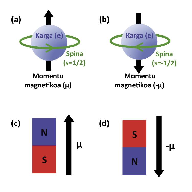
In this thesis for this change we have proposed the spintronic option, which is a new field of electronics that takes advantage of the charge of the electron and its spin. Spin is a quantum property of elementary particles and can be represented as an intrinsic and quantized angular moment, that is, as a spin that can take unique values in a given direction. In the preferential direction Z, the spin takes the values s = ½ and s = -½ (ascending and descending), that is, if we represent the electron in a classical way, we would represent it as a particle that rotates up or down.
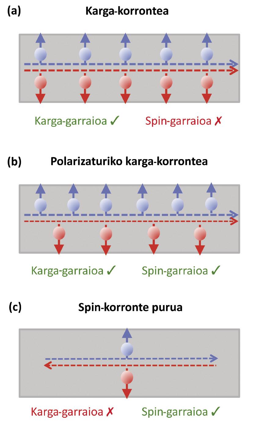
Since the electron is a charged particle, it has a magnetic moment associated with spin:>. This means that the electron behaves like a microscopic magnet. In fact, the magnetization of magnets and/or ferromagnetic materials (FM) is due to the fact that these materials are oriented to a certain direction of spines. Therefore, when a load current is transported through an FM material, it is usually polarized: the spines of the electrons that carry the current are also aligned. As can be seen in figure 2, executing the same load transport, in the case of polarized load more information can be transported (from the load and spina), so that consuming the same amount of energy the data process is streamlined.
Spintronic was born in the late eighties and has had diverse applications. They are based on the generation of polarized currents, transport at short distances and detection, for example, devices that read information stored on hard drives. At present, however, the development of spintronics will come from second-generation devices that will replace the load current with a pure spin current to reduce heat losses caused by the Joule effect and the consequent energy consumption. As can be seen in Figure 2(c), the presence of a pure spin current considerably reduces the heat loss caused by the friction of the same by a polarized load current. Note that the spin current is defined as JS = J - J, where J and J are the load currents associated with the ascending and descending spin, the descending spin going to the left is equivalent to the upward spin going to the right, so the spin information being transported in figures 2(b) and 2(c) is the same.

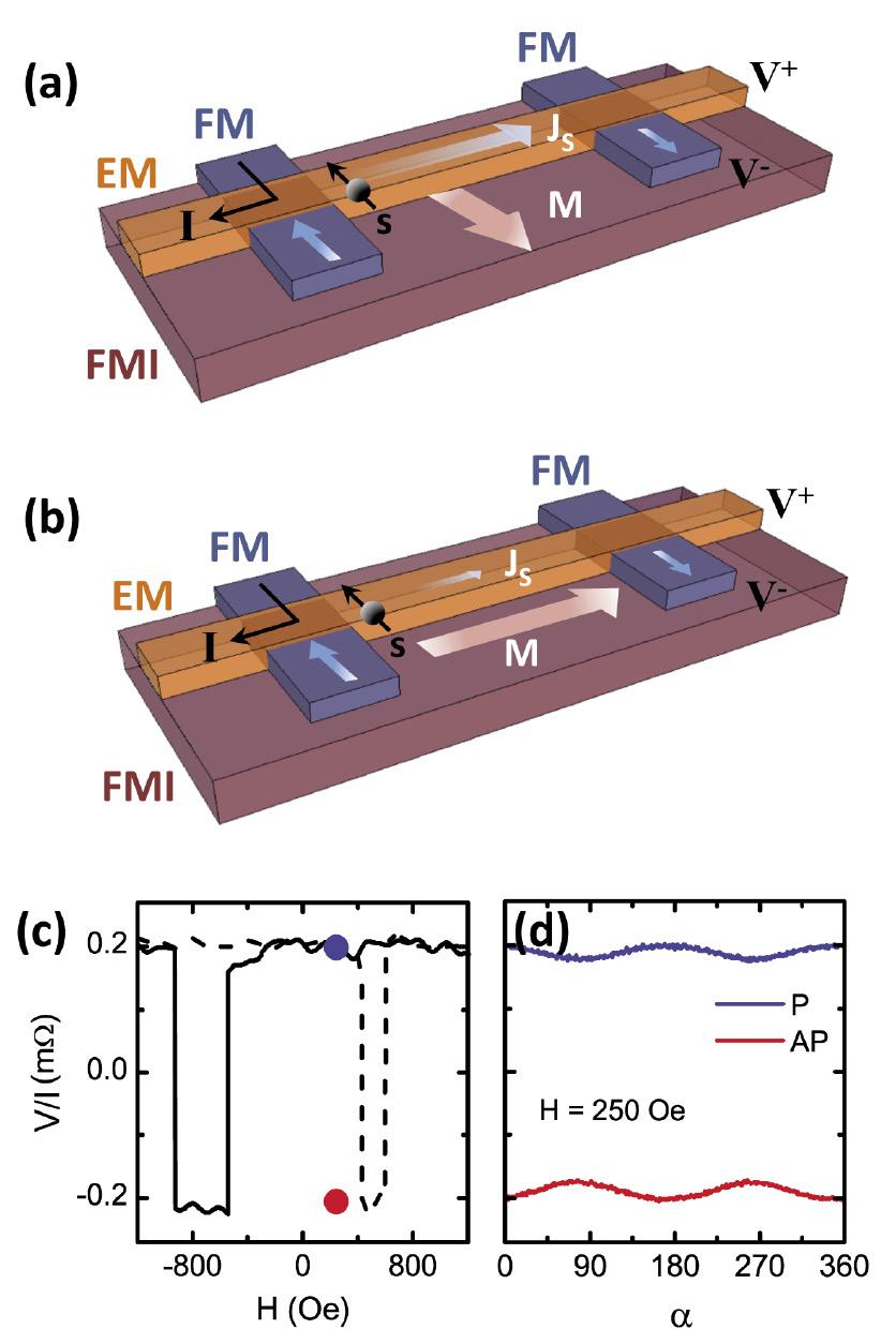
For proper operation of second generation spintronic devices, three elements are needed mainly: (i) generation of pure spin currents, (ii) transport of such currents over long distances (>100 nm) and (iii) handling of conveyed spines. Therefore, the objective of this thesis has been to analyze these elements using side spin valves. Side spin valves are devices that allow pure spin currents to be generated electrically. Two FM electrodes consist of a non-magnetic channel (MRI) that connects the two FM electrodes and the same ones, and their geometry allows to direct an electric current from an FM electrode to an MRI channel, while measuring the voltage through the second electrode, as indicated in Figure 3(a). The current of the first FM electrode to RM channel is polarized along the FM, but since the RM material has the same number of ascending and descending spines, spines from FM find a resistance on the surface between the two materials, where they are stacked in imbalance. To balance the system, these stacked spines extend to both sides of the FM electrode, generating a pure spin current in the part that we do not have load transport. The second FM electrode allows between the RM channel and this FM to occur again an accumulation of spines that can be measured as an electrical voltage. Therefore, although we might think that the voltage measured as the charge current does not move between the two electrodes must be null, there is a measurable electrical voltage created by the pure spin current or spin signal. The relative magnetization between two FM electrodes modifies the sign of this tension: when the magnetization of the electrodes is parallel (in the same sense of the magnetization of both), the tension is positive, but when its magnetization is antiparallel (when the magnetizations have opposite senses) the measured voltage is negative. Electrode magnetization can be controlled by an external magnetic field. Thus, measuring the tension according to the external zone, we obtain the curve of figure 3(b), fingerprint of the lateral spin valves.
The side spin valves are so small (the electrodes, for example, have an approximate width of 100 nm) that if a particle of dust falls on top they can stop working. Therefore, they are manufactured in a laboratory called “white room” where the number of particles that can be in the air is well controlled thanks to special filters. For the manufacture of the samples the technique called lithography by electron cannon has been used. This technique consists of “writing” on a polymer with an e-cannon and evaporating the metal. This technique consists of several steps: first it extends on a substrate (usually silicon) a polymer sensitive to electrons (what is called resin); then, through the e-cannon, the image that is desired to be obtained is written and revealed using a chemical, that is, the written resin is removed. The metal evaporates on it and finally the whole sample is inserted into the acetone to dissolve the resin, keeping the metal only in the area indicated by the e-cannon. In our case, we have performed this process twice, first to generate the FM electrodes and then put the channel above the MRI. In each sample different spin valves have been placed, measuring the spin signal for different RM channel lengths, to understand the properties of these devices. Finally, thanks to optical lithography (replacing the e-cannon with ultraviolet light) the macroscopic pathways shown in Figure 4(d) for the electrical contact of the sample have been created.

The high repeatability in the manufacture of our devices has allowed us to use different ferromagnetic materials to generate pure spin currents, obtaining the maximum signal with permalloy (iron nickel alloy). In addition, analyzing the transport of spin through the cave depending on temperature, magnetic impurities and defects (surfaces, grain limits, etc.) They have been identified as responsible for reducing the spin signal. Interestingly, although we need nanometric structures to measure spin signals, its small dimension increases errors while hindering the transport of spines.
Finally, a new spin-handling method has been proposed and developed through the interaction between spines and insulating ferromagnetic materials (IMF). As these materials are insulating, they do not carry electrons, but their magnetization (M) affects spines that circulate through channel MRI, when it is perpendicular to them. M is easily controllable by a small external magnetic field which, being small, does not affect the magnetization of the FM electrode. Thus, when the polarization of M and spines(s) are parallel we do not measure changes in the spin signal, while when M and s are perpendicular to each other, the IMF absorbs spines and the measured signal is less. To check the proposed method, we have manufactured the lateral spin valves on an yttrium and an iron garnet and, changing the direction of M with the angle <unk> (but keeping its fixed value at 250 oersteds), we have detected an 8% modulation in the measured signal for parallel and antiparallel magnetization of the FM electrode. This modulation is totally evident and it is considered that, both optimizing the manufacturing process and selecting the right materials, it can be significantly increased. In this way, we have opened the way for logical operations with pure spin currents. This is an essential requirement if we want to replace conventional electronics with spintronics that flows thanks to pure spin currents.
Bibliography

Buletina
Bidali zure helbide elektronikoa eta jaso asteroko buletina zure sarrera-ontzian