


Microstructural design of ceramic and cermets for tools
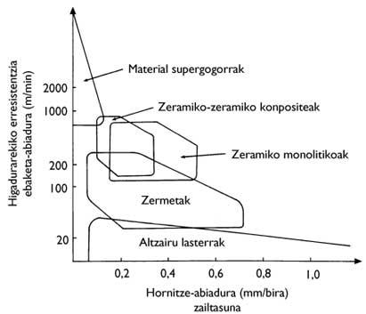
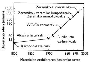
Current technology continues to increase cutting speed (Figure 2). From the point of view of cutting tools, this increase in speed generates two main effects: on the one hand, the tensions that the tools must withstand are increasing and, on the other, the temperatures that are reached during cutting are increasing. For these adverse conditions it is necessary to use suitable materials, that is, resistant materials and resistant to high temperatures. Difficulty is also important in non-continuous processes, as materials must be able to withstand mechanical shocks.
This paper will analyze the microstructural design of ceramic and tool cermets, since the properties of these materials are suitable to the harsh cutting conditions mentioned. Due to the lack of difficulty of ceramics, the characteristics of these materials have not been understood or used correctly. However, in the last decade more research has been done on these materials than in the last 40 years. The development of the fences has been completely different, with the use of cemented carbides for a long time. However, because the design of these materials has a lot to do with the problem of ceramics, it is advisable to analyze them together. On the other hand, in order to clarify some aspects of this work, metallic materials have been compared, since the behavior of these materials is better known to all.
From compounds to material: microstructure
Structural ceramics are based on chemical compounds such as: nitrides (Si 3 N 4, TiN, ..), carbide (WC, SiC, ..), rust (Al 2 O 3, ZrO 2, ..) and boruro (TiB 2, Zr2, mainly ...). Since these joints are very resistant and directional, the crystallographic structures of these compounds are very resistant and rigid (almost indeformable), maintaining these properties at very high temperatures. In addition, these compounds, due to their chemical stability, are capable of machining virtually any type of material. However, the characteristics of structural ceramics are not only present in the compounds but also in the microstructure.
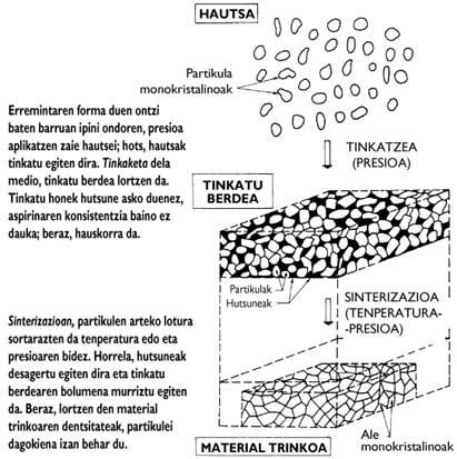
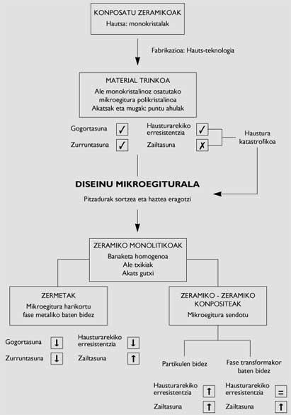
In general, ceramic manufacturing is done by powder technology (Figure 3), at the beginning of the process, using components of materials (chemical compounds) as powder. Because the particles of these powders are monocrystals of the compound, their behavior is intrinsic. The manufacture of structural ceramics from these powders is limited to the generation of connections between particles. The latter is achieved by fixing and sintering powders. In these two processes, temperature and/or pressure allow to obtain a compact material consisting of monocrystalline specimens.
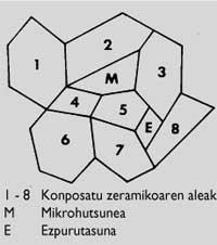
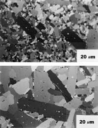
In the ideal process, there should be no gaps between particles in the entire volume of the material, so the density of the material should correspond to the chemical compound. Unfortunately, pores can often be found along the volume of the material. Impurities from the manufacturing process may also exist (Figure 4). On the other hand, the so-called dimensions, morphology and distribution of the specimens condition the connections between them. Therefore, the aforementioned aspects define the microstructure. Therefore, materials made with the same compound may present different microstructures (Figure 5).
Due to the distortion of the spatial distribution between the elements both in defects of the microstructure (gaps and impurities) and in the boundaries between the grains, their connections are slower than between the atoms inside the grains (Figure 6). Therefore, limits and defects are weak points of the microstructure. This makes the mechanical properties of materials worse than those of their monocrystalline components (chemical compounds).
Ceramic problems
In the field of structural materials, mechanical behavior is described with the following properties: hardness, stiffness, breaking resistance and difficulty.
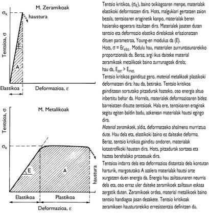
Due to the hardness of the ceramics, they are very suitable materials for the manufacture of cutting tools of high wear resistance. On the other hand, their rigidity makes their deformation very reduced when they are under the tension zone. Figure 7 shows that ceramic materials are able to withstand higher stresses than metallic ones.
However, the problem of the applicability of ceramic materials lies in their behavior against breakage. As indicated in Figure 7, overcoming the maximum tension supported by the ceramics allows an immediate break of the materials. Due to the lack of deformability, these materials cannot adjust the “surplus” voltage. Therefore, ceramic breakage is catastrophic (like when a plate falls to the ground). The metal materials, once the corresponding maximum voltage is exceeded, are plastically deformed before breaking. These materials make the tensions adapt by deformation, since the microstructure grains are ductile. As an example, in case of impact, the steps that occur in cars can be cited.
Process performance is very important in any industrial activity. Therefore, from this point of view, the tools that break catastrophically seem inadequate. However, given that the other properties of ceramic materials are very suitable, an important scientific effort has been made to improve the behavior against the breakage of ceramics.
The parameters that define the break are the breaking resistance (which indicates the maximum stress supported by the materials) and the difficulty (which is proportional to the energy absorbed by the materials at the time of their breakage). Of course, the low difficulty of ceramic materials is the biggest problem in cutting operations.
As discussed above, the behavior of materials must be defined on two levels: chemical compounds and microstructures. Since the intrinsic behavior of chemical compounds is immutable, the only way to improve mechanical behavior is by changing the microstructure. For this it is convenient to know the breakage procedure.
Two processes are involved in material breakage:
- crack formation (when critical stress is overcome)
- increased fissures (taking advantage of the energy supplied by the tension zone)
Ceramic Design Basics
Taking into account the processes involved in the rupture, we can conclude that:
- the harder it is to create cracks, the greater the breaking resistance
- the greater the energy absorbed by fissure, the greater the difficulty
As for monolithic ceramics, the following have been acted upon. On the one hand, microstructures are getting cleaner, that is, microstructures with few defects. In this way, the probability of cracking decreases and the resistance to rupture of the microstructure approaches the value corresponding to the monocrystalline grain. Also, if defects are further away from each other (due to their low presence), the material must absorb more energy so that cracks grow, since the growth of cracks is due to the interconnection of microfibers generated in defects. Therefore, you can also improve the difficulty. On the other hand, microstructures are getting thinner and thinner, since the smaller the grains, the greater the resistance to breakage.
To achieve the two stated objectives, the powders used are of high purity and reduced particles. In addition, sophisticated manufacturing techniques are being used to ensure that densification is complete and stresses are not contagious.
While the mechanical behavior of monolithic ceramics thus obtained is significantly better, it is not the only way of design. In fact, monolithic ceramics have developed ceramic and ceramic metal composites.
Ceramic and ceramic composites
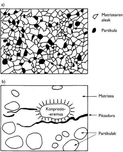
These composites consist of two “ceramic” compounds. The granular structure composed of the largest number of compounds is called the matrix. The specimens of the other compound are distributed homogeneously throughout the matrix. Depending on the function of this second phase two ceramic cutting materials are mainly distinguished:
- Particle reinforced
- Reinforced by a transformable phase
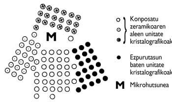
The specimens of the second compound of composites reinforced by particles, being not united with each other, are called particles (Figure 8). Because matrices cause a force against particles to disperse external stresses, they depend on a compressive tension zone. Therefore, to withstand the tension zone, particles must be more rigid than matrices. This tension field prevents both crack formation and crack growth. As for the formation of fissures, because the particles become points of accumulation of tensions, the material can withstand greater tension.
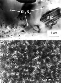
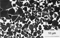
On the other hand, the appearance of cracks makes the particles difficult the growth of cracks, since they cannot cross the tension zone that surrounds the particles. Therefore, when approaching a particle, the fissure changes direction (Figure 8). Thus, the road that the cracks must travel is much longer and the materials must absorb more energy, that is, the difficulty is greater. In this field, the composites Si 3 N 4 (Figure 9) are reinforced with SiC and SiC particles reinforced with TiB 2 particles.
In composites reinforced by a transformable phase, the second ceramic phase surrounds the grains of the matrix. This second phase is in a metastable situation. Thus, when subjected to critical tension, this phase is transformed into its stable state. The absorption of energy in this transformation increases the difficulty of the composite. Moreover, in some cases, along with the transformation, the volume of the second phase also increases.
This phase then produces compressive forces over the main phase. Therefore, comparing with composites reinforced with particles, although an opposite effect occurs, the same effect is achieved. Thus, cracks must absorb more energy to traverse these areas of tension. Therefore, this is another way to improve difficulty. In these ceramic ceramic composites the resistance does not increase, since the cracks are generated under the maximum tension that the matrix can withstand. In these ceramic ceramic composites, the reinforced Al 2 or 3 can be cited by the transformable phase ZrO 2 (Figure 9).
Ceramic and metal composites: cermets
The basis of the design of these materials is very simple, that is, it consists in providing the indeformable ceramic specimens with a capacity of dispersion of tensions. To do this, the fences, around the hard grains, present a ductile phase that makes the tensions change. Of course, this ductile phase is metallic and the fences are hybrid between ceramic and metals. Therefore, the resistance, hardness and rigidity to the break of the fences are lower than the ceramics, while the difficulty is much greater (Figure 7).
To make the pair “Ceramic Composite Ductile Phase” suitable it is necessary to meet a number of requirements. That is, that the hard and metallic phases are chemically compatible. On the other hand, to compact the material, the two phases must adhere to each other. The couples that meet these requirements are made up of carbides (WC, TiC, TaC, ..) and boruros (TiB 2, ZrB 2, ..) of some transition metals and the Fe, Co and Ni of group VIII of the first period of transition metals.
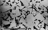
In these hybrid materials we must mention the cemented carbides WC-Co, which were the first (invented in 1929). The metal phase is liquid in the sintering of these materials. In this way, in the refrigeration the solid ceramic specimens are fixed in the microstructure. Since the liquid phase acts as cement, these cermets are called cemented. Based on the WC-Co pair, the family tools (WC, TiC, TaC)-(Co, Fe, Ni) are the most used in the steel cutting processes, being the main components WC and Co mentioned (Figure 10)
Looking forward
Due to the momentum given in the field of ceramics, many of the existing ceramic tools in the current market are specially designed for some cutting applications. Leaving monolithic ceramics almost behind, they investigate the sophisticated designs of ceramic and ceramic composites. That is, by controlling the morphology, size, orientation, distribution and other variables of the particles, you can obtain ‘favorite’ microstructures of each of them. Therefore, the current trend is to continue the design of ceramic materials according to the mechanical properties required by industrial needs.
As for the requirements, TiB 2 -(Fe, Ni) investigates his new family (Figure 11). This cermet is intended to replace both cobalt and tungsten carbide. Cobalt production is in the hands of very few states, because it is a strategic element. Cobalt powder, due to its carcinogenic origin, is also very dangerous. On the other hand, since the TiB 2 compound is more resistant than the WC, the TiB 2 (Fe, Ni) tools they have already tested, have shown better behavior than the “classic” cermet in high-speed cutting processes.
Buletina
Bidali zure helbide elektronikoa eta jaso asteroko buletina zure sarrera-ontzian