


Travel simulation in power converter design process
The use of computer simulation is widespread in different areas of science and technology. In many cases, the systems to be analyzed are often very complex and it is very difficult to obtain analytical solutions. In these cases, one of the solutions is computer simulation.
When you want to simulate a real system, you must first define the equations that describe the dynamic behavior of that system. These equations generate a system model on the computer. In this way it is possible to analyze the functioning of the system, modifying the values of the variables can make predictions about the behavior of the system.
Drills are performed step by step. In each simulation step, equations describing the behavior of the system are solved using integration algorithms (Euler, Runge-Kutta, etc.) Based resolutions are applied (solver). In addition, each simulation step has a simulation time. This time indicates whether the simulated system can be both in the real world and sometimes. To determine this simulation time, the resolutor adds to the simulation time of the previous step a certain time, called step length.
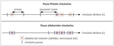
Basically, resolvers can be divided into two large groups: those executed at a fixed step and those executed at a variable step. A simulation is said to run at a fixed step when the length of the step is kept fixed throughout the simulation. On the contrary, in variable step simulations, the length of the step varies depending on the dynamics of the system. In this sense, the simulation step is shortened if in a certain period of time the system changes considerably, thus improving the accuracy of the simulation. However, in times of little variation, the passage lengthens. To determine the length of the step, variable pitch resolutors use special algorithms. This allows efficient control of the number of steps to be taken.
Simulating switches
There are currently power converters everywhere, such as ships, windmills and electric vehicles. Power converters are used in energy conversion systems, which aim to transform electrical energy in a controlled manner. In this sense, computer simulation has an important role in the first parts of the design process of these converters, since it allows analyzing the behavior of the converter before building the physical prototype.
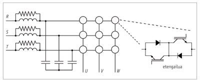
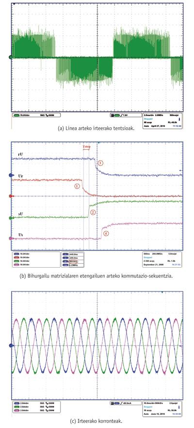
Normally, power converters are formed by switches (which are built using semiconductor devices) and their configuration allows the construction of different topologies (rectifiers, matrix converters, etc. ). It is considered that the switches are controlled when it is possible to control the activation or deactivation moments. Thus, using the appropriate control and modulation algorithms, it is possible to properly control the activation and deactivation moments of the switches. In this way, the converter can synthesize in its inputs and outputs voltage and current references established by the control.
There are several simulation options for power converter switches. On the one hand, equations describing the behavior of semiconductor devices can be used, and on the other hand switches can be considered ideal. The use of specific mathematical models of semiconductor devices is very useful when it comes, for example, to analyze the efficiency and losses of the converter. However, the complexity of the model to be simulated increases considerably, so it takes too long to perform simulations. On the contrary, if the objective is the analysis of the converter control system, it is enough to consider that the switches are ideal, that is, when they are switched on they create a short circuit and when they are switched off they remain in open circuit.
The simulation of switched systems, especially power converters, has its challenges. For example, if a fixed pitch resolutor is used, it is clear that switching instants and switch simulation steps need not be synchronized. Therefore, if a switch needs to be activated between two simulation steps, the simulation does not take into account the effect of such activation until the next simulation step. These errors result in the appearance of low-frequency harmonic components in the currents and voltages synthesized by the converter. These harmonic components are produced as a result of the resolution used and have nothing to do with the actual behavior of the converter. This phenomenon is called jitter (i.e., irregular disturbances). However, the error can be reduced if the length of the step is reduced, in return the simulation slows down considerably by considerably increasing the number of operations to be performed. With variable pitch solutions it is possible to compensate the jitter without moderating the simulation.
Accompanying interpolation
Control algorithms in modern power converters are increasingly complex. At the same time, switch switching frequencies are in many cases very high (the matrix converter is a good example of this). Therefore, despite using resolvers with variable steps, simulations remain very slow. Consequently, the number of simulations that can be carried out in the design process in the absence of solutions is very limited.
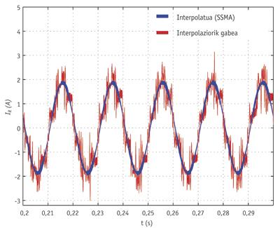
In these cases, the best solution is to use interpolation techniques. Interpolation allows to approximate the value of variables at a point between two simulation steps. This way you can increase the length of the step while maintaining good accuracy. However, a compromise must be sought between the length and accuracy of the step, since the longer the step, the simulation is faster, but at the same time the accuracy is lost. There are several interpolation techniques such as TAM (Time Averaging Method), SSMA (Switching State Matrix Averaging Method) and linear interpolation. For example, using the SSMA interpolation technique instead of a variable pitch solver to simulate the matrix converter saves 95% of simulation time.
Simulating in real time
As already mentioned, in the early stages of the design of power converters and their controllers, the computer simulation standard plays a very important role. On the other hand, there is another type of simulation, called real-time simulation, very useful for the last phases of the design process.
When a certain model runs at the same pace as the real world, it is said that that model is simulated in real time. That is, when you run a simulation step, the simulation time corresponding to that step matches the time elapsed in the real world from the start of the simulation.
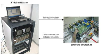
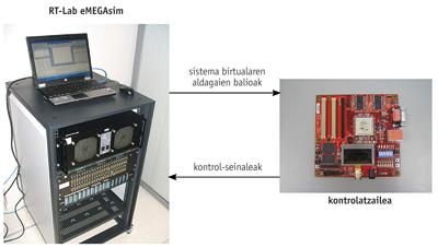
In order to simulate in real time it is necessary to solve the equations to be solved in each simulation step before starting to execute the next simulation step. The complexity of the calculations needed to simulate power converters makes it necessary to use special high-capacity calculation devices that allow their simulation in real time. Since the beginning, hybrid DSPs and simulators (with analog and digital parts) have been used to simulate real-time power systems. However, microprocessor-based technologies have been very well received in recent years. Examples of this are Hydro Quebec's Hypersim supercomputer and Opal-rat's RT-Lab eMEGAsim real-time digital simulator.
Basically, these microprocessor-based digital simulators are cluster groups. These systems use parallel computing to achieve a very high computing capacity. In these systems it is mandatory to use fixed pitch resolutors, since variable pitch resolutors are not determinists (you cannot know how long it takes to solve each step). On the other hand, the minimum step length is limited by two factors. On the one hand, the step must be long enough to perform all calculations, and on the other hand it must be greater than the delay due to communications between microprocessors. For example, in real-time simulation of many power converters, the minimum pitch length in eMEGsim is 10”, so the pitch length is relatively large, so interpolation techniques are needed to get concrete results if you want to simulate power converters in real time.
These real-time simulators have analog and digital inputs and outputs. In this way, the simulated model in real time can communicate with the real world. Likewise, the simulator must be able to calculate the errors due to the lack of synchronization between the switching signals and the simulation steps that it can receive from the digital inputs, information necessary for the correct execution of the interpolation algorithms. At the same time, it is important that the simulator can send switch activation and deactivation signals with great precision through digital outputs. For example, these functions can be performed using FPGA (Field Programable Gate Array) fast digital devices. These features enable two real-time simulation modes: rapid prototyping control and real-time simulation Hardware in the Loop (HIL).
Rapid prototyping control is a well-known methodology that has been used for several years in the design of converter control algorithms. In real systems ready to market, the control is implemented on a given electronic device. In rapid prototyping control, on the contrary, the system control simulates in real time in the digital simulator and the system you want to control, in this case the converter, is real. The digital simulator connects to the physical prototype in a closed loop. In this way, the simulator collects the values of the variables to be controlled from the real prototype and at the same time sends to the converter signals of activation and deactivation of switches. This technique allows us to bridge the gap between simulation and the real world, reducing the converter design process and reducing time to market.
On the other hand, real-time HIL simulation has been widely used in automotive and aeronautics. However, the practice in power electronics is relatively new. In this mode it is done just the opposite of what is done in rapid prototyping control, that is, the converter simulates, while the controller is real. This executes in real time the faithful model of the system that you want to control in the digital simulator, and is controlled by a real controller. Real-time HIL simulation is very useful in the design process of converters, as it allows analyzing the operation of the physical controller in normal and extreme operating conditions of the system without endangering any expensive prototype.
As can be seen in this article, simulation is an excellent working tool for the design of power systems with different possibilities.
Bibliography
This work was carried out with the support of the University of the Basque Country/Euskal Herriko Unibertsitatea, the S-PE09UN08 SAIOTEK project of the Basque Government and the grants (IT394-10) to promote the activities of the research groups of the Basque university system of the Department of Education, Universities and Research of the Basque Government.
Buletina
Bidali zure helbide elektronikoa eta jaso asteroko buletina zure sarrera-ontzian