Electric drives in the era of robotics
1987/06/01 Sagarna, Andoni - Ingeniaria Iturria: Elhuyar aldizkaria
Pre-automation actuators
Machine automation is experiencing a breakthrough in the last two decades. Electronics and computing are always the engine of these advances. And it is that the innovations that mechanics can make are much more limited. However, among the "brain" that composes the electronics and microinformatics and the organs of support and movement that the mechanics offers there are other organs that, without great uncertainties, are making a great advance: the actions.
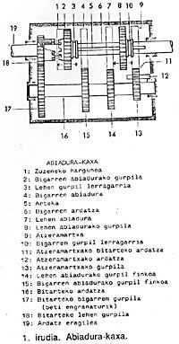
To be able to modify the speed of the mobile organs of the machines before the automation came, fixed speed electric motors and gearboxes were used. In them were combinations of gears that were manually changed
Contribution and evolution of the motors of direct current
Electric motors are those of direct current which offer greater ease to vary the speed. In the advances of the machines, these engines have allowed to remove the gearboxes.
A conventional DC motor contains a coil that produces a magnetic flux by direct current in the fixed part called a stator, called an inducer.
The rotating part called rotor has another coil known as induced.
The mechanical characteristics of the motor shaft are the turning point M (measured in Nm) and the turning speed n (measured in s -1).
The relations of these mechanical magnitudes with the electromagnetic ones, easily understandable, are:
M = K 1 I
n = K 2 V - IR
where:
- V = voltage applied to the induced, I = induced current, K 1 and K 2 = constants corresponding to the structure of the machine and R = electrical resistances of the induced circuit.
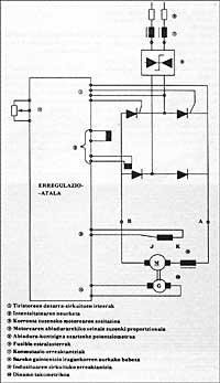
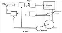
From the alternating current of the power distribution network (let's say 380 V - 50 Hz), the variable voltage in direct current is obtained by rectifiers formed by tiristors. See figure 2.
For easy understanding, the axis requires a current I to give a turning point M (constant). To modify the rotation speed n in these conditions it is necessary to modify the induced voltage U.
An important advance in the motors of direct current has been the substitution of the inductor fed by direct current by permanent magnets.
The advantages are evident:
- No inductor coil or voltage source or circuit is needed to feed it. Elimination of power losses in the inducer. In this way, when the engine is heated equally, a greater turning moment is achieved. The moment and rotation speed ratio becomes linear facilitating regulation. Smaller engine size.
- More pole motors can be built, obtaining very low speeds without vibrations.
Large changes have occurred in the permanent magnets themselves. Initially they were ALNICO alloys (Aluminium/nickel/cobalt/titanium/iron), then ceramics and later rare earth (samarium, cobalt, etc. ). (with). This advance allows to obtain large M in accelerations and deceleration thanks to the use of large I, since magnets are made increasingly difficult to demagnetize.
Obviously, in the current robots the dynamic characteristics are good, short response times, or the moments of inertia J and the great turning moments M are indispensable. Remember acceleration Remember acceleration
being = /J.
Coal-free engines (Brushless motors) and electronic controls for
All the engines of direct current mentioned so far require a collector in the rotor and coal in contact with it. It is the section that generates more headaches to users of motors of continuous current: sparks, wear of coal and collector, few dynamic characteristics, noise, etc.
This set is a mechanical switch. If this switching is done electronically outside the machine, no coal or brushes are needed.
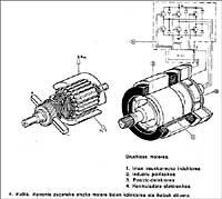
Based on this principle the so-called brushless have been created. The main parts of the engine have been inverted with respect to conventional motors of continuous current: the induced one is in the stator and the inducer (realized with permanent magnets) is rotable:
Since there is no mechanical switching, the motor can be fed with the network voltage, since the power of the iron is the only ones in the stator can be used efficient cooling systems, the winding is done with ease (even automatically) and the protection of this winding with the temperature measurement probe is simple. All of them are great advantages. The sangria is in the construction of the rotor, especially in the selection and assembly of magnets. Rare earth magnets are much more expensive than ceramics, but when small dimensions and good dynamic features, such as robots, are needed.
Another problem is that these magnets stick reliably on the rotor.
We could deepen a little more in the comparison between the motors of direct current and the brushless. Some say that brushless engines are direct current motors with electronic switching, but from a constructive point of view it would be more correct to affirm that they can be synchronous motors of alternating current, which is the structure of synchronous machines
These coal-free motor drives are formed by a synchronous motor and a static (electronic) regulator that feeds it, being the feeding phase associated with the rotor position.
In the motors of direct current, the collector is mechanically joined to the induced one, switching the current from the circuit according to the position.
Regulation of Bruhless engines
The characteristics of the motor and the basic electronics connected from the outside can be seen in the following scheme of principles:
Senoidal electromotor force motors for actuating axes
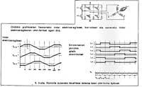
A sinusoidal electromotor force motor with a three-phase (usually transistor) converter is powered in numerical control machines and flexible production systems.
In most cases, a system of these characteristics has two control nodes. See figure 6.
The interior is a softening of current. The mechanical time constant of the system does not affect the response time of this fleje. That's why it's very fast and it's a bigal turning. This allows maintaining the shaft without speed variations at low speeds.
In most cases the system is formed by a bigal position.

Gai honi buruzko eduki gehiago
Elhuyarrek garatutako teknologia


