Ferrería de Agorregi
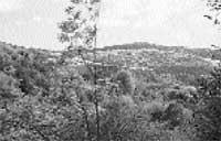
As the march progresses, the whirlpool of water takes us to the Agorregi ironworks, a historical heritage that is preserved in the old buildings. In it water predominates, the main function of the ironwork is to make the most of the water. Despite the fact that the Agorregi ironworks ended a long time ago, today it is much more than a mere curiosity: the ironwork is an advanced technology building that served to adapt the resources of nature to human needs, in the name of progress, but respecting the laws of nature.
We soon learned about the system used by the Agorregi ironworks. But before we start, we dive into the historical journey of the ironworks.
Agorregi Historical Park
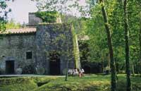
Since the Middle Ages, the force of the streams descending from Mount Pagoeta is known. At this time belong the first documents of the Agorria ironworks, preserved in the Diputación Foral de Gipuzkoa. According to this data, in 1470 Henry IV of Castile recognized Mr.Juan de Abedaño the rights on the ironworks through legal privileges. At this time the activity of the ironwork was intense and its influence stood out in all the environment.
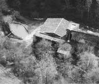
Around 1530, when there is no specific date, the activity of the forge slowed down and closed completely. The rebirth represented great technological advances and the ironworks of Agorregi was not able to compete with them. In any case, a forge was not completely discarded and a mill continued to work; XVII. In the twentieth century another mill was built.
Around 1754, new buildings began to be built. The responsibility for the change of design fell on Joakin de Lardizabal, head of it, and although the structure of the old forge was basically respected, this fact launched new future uses. The two main activities of the area were definitely refused: steel and milling.
In addition, at this time, a design was launched to make the most of the water scarcity in the basins. For this purpose the architect Francisco de Ybero de Azpeitia was assigned the responsibility of the design change. From this time, the systems that would later be used with great success in the Agorregi ironworks, such as the distribution of slopes and the design of the channel. Later the saw was installed and finally the mill was built at the base of the ironworks.
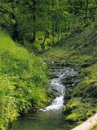
The ironwork that can be visited today gives us direct testimony of this time. The structure of the ironwork, the tooling, the distribution of the tools and the storage systems were designed to adapt to the needs of the time, and thus remained until the total exhaustion of the activity of the ironwork. Why did it happen? What caused the failure of this construction? The truth is that there is no reliable data. In the old documents preserved in the Diputación Foral de Gipuzkoa there is no answer to these questions. However, references to possible problems derived from this design have been found, and throughout the archaeological excavations carried out in the workshops, the design defects of the ironwork have been evidenced.
As mentioned above, the Provincial Council of Gipuzkoa assumed the restoration of the Agorregi ironworks. The works began in 1986 and continued until December 1991. In addition to the recovery of buildings and cleaning of channels, the XVIII. It has been achieved to work with the same design that was built in the mid-twentieth century.
Agorregi basin
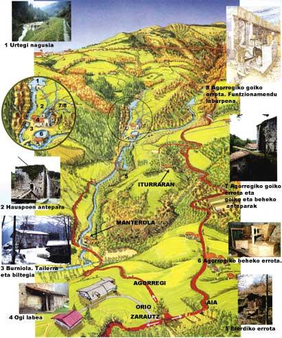
This basin has a small extension, about 5 km 2 approximately. The streams are short, coming down little by little from Mount Pagoeta. The streams only carry about 40% of the rainwater and the rest is lost by evaporation or by absorption of the surrounding plants.
Three streams converge in the valley of Agorregi: D. D. Pedro Zulo, Erregaiturri and Mindi. In two of them, in Laukaiturri and Mindi, there is a reservoir before arriving in Agorregi to fill their slopes or water deposits.
In fact, the Agorregi forge consists of two ramps, one on the other. When water is drawn from the upper slope, the potential energy generated is transformed into kinetic energy, so that, by means of a wheel, it moves the central axis of the ironwork machinery. The water that has been left without energy is directed to the bottom slope, allowing the reuse of water. This system, designed by our former ones, achieved the maximum profitability of water for its subsequent use in the ironworks and mills.
Description of the streams
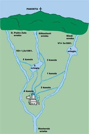
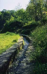
When arriving at the ironworks, in order to achieve the maximum utilization of the waters of the rivers, the water of Laukaiturri and Mindi is diverted through the channels
The Mindi channel leaves its reservoir and is divided into two, one of the branches (Canal 1) that heads to the top and the other (Canal 2) to the bottom. The stream itself runs through the area of the forge following its route.
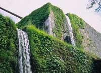
The Erregaiturri stream also has two channels (3 and 4). The first (Canal 3) leaves the river about a hundred meters before reaching the reservoir, while the second (Canal 4) leaves the reservoir itself and heads towards the lower slope. This second channel has a Chinese, that is, a gate or gate that keeps water flow stable until the wheel.
D. D. The Pedro Zulo stream has a single channel (channel 5) from which it pours its waters to the reservoir of Laukaiturri. D joins a little earlier than where he joins Mindi. Regata Pedro Zulo.
Operation of the ironwork
The Agorreta Ironworks is a building formed by two reservoirs, five canals, two slopes, workshop and warehouse.
For the operation of the forge, two hydraulic wheels were installed. The water of the upper shelf was extracted from the Chinese on the wheel of the bellows and, to control the process, ordered the opening of the Chinese from the own workshop of the ironwork. For the wheel to start spinning, it needed an approximate water current of 80 liters/s. The movement of the wheel was transmitted by means of the mechanism that appears in the drawing to two great bellows that alternated the air intake. In this way the air needed to melt the iron ore at high temperature in the oven was obtained and the fire was lit at full speed. On the other hand, to direct the water to the most suitable turning point of the wheel, the water that fell from the Chinese was passed through an evicted trunk, the so-called “ark of the lie”.
Mechanism of mechanism
The wheel that was propelling the bellows was joined by a long chain. The end A of the chain was far from the axis of the wheel at a specific point. When the wheel started to rotate, the B-end of the chain went up and down and transmitted this upward movement to the first trunk (Trunk 1). A second trunk held the first in half. This second trunk (Trunk 2) was fixed on a wall and completely static, aligned with the motion plane of the first trunk.
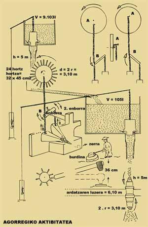
At the ends of the first trunk the bellows were joined by two short chains. The alternative movements that the chains transmitted to the bellows were more or less vertical. The air outputs of the bellows, on the other hand, met at the entrance of the mineral deposit and thus managed to keep alive the coal fire.
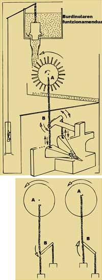
As mentioned above, the water used for the propulsion of the first wheel was directed towards the lower slope, where the second wheel was moved by the same system described. However, the flow of 80 liters/s needed to cause the rotation of the first wheel was necessary to double to cause the second spin. The second wheel moved a large hammer for which the water pressure should be 0.5 kg/cm 2.
This second part of the mechanism, located at the bottom of the workshop, was transmitted to a central axis the movement of rotation of the wheel and the teeth of the axis at its end raised the hammer of the forge. And after all this, the water of the lower slope was reused, this time to drive the wheels of the old annex mill.
October to June:
Summer: Summer:
|
Let's play with the Agorregi forge
The water flow indicates the amount of water that passes through a section of the channel in a given unit of time. We measure it in liters/second.
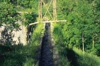
To calculate the water current, in point 1 a cork is released and, dragged by the water current itself, it takes the time necessary to reach the 10 meters of travel, that is, 2 points.
t = = = = = = = = = = = = = =
Logically, in this period, we can also calculate the volume of water that has passed from 1 to 2 points:
V = a . b. c.
where:
a = channel depth b = channel width c = length of travel in this case 10 meters
And now reader, expressing in dm 3 that value that almost calculates.
To obtain the values a and b, we give for good the average of some different measures. On the other hand, assuming that the movement of the cork is direct and stable, its speed will have the following value:
v = c/t (dm/s)
Then, to express the current, we will use the following formula:
Flow rate = volumin-time = a.fere / t = a.b/c/t = a.b.v
a.b = S
Flow rate S . v (dm 3 /s = l/s)
where:
S = Section channel v = water speed
The sum of the channel flows that arrive at the top slope will not be sufficient to move the wheel from the bellows, that is, to the 80 liters/second mentioned above does not arrive the sum mentioned. This indicates that for the system to function properly, the slope has to accumulate more water.
Another small exercise is to take the avenues up and down in spring, autumn, summer and winter.
Analyzing the upper slope
The water mass center of the slope is located about five meters from the wheel, always under the zone of gravity of the Earth. Due to the height from the surrounding, the accumulated water has the mechanical working capacity, that is, it can move the wheel when falling. This capacity is called gravitational potential energy. The formulation is as follows:
Ep = m . G. g. h)
where:
m = water mass (kg) g = gravity acceleration g = 9.8 m/s 2 h = height (m)
The water, by free fall, reaches the wheel at high speed. As it is often said, its potential energy is transformed into kinetic energy: the water capacity to perform a mechanical work by its speed. The water transmits its kinetic energy to the wheel when it comes into contact with the teeth and thus the wheel will begin to turn.
Suppose that in all this process 85% of the initial potential energy of the water is used to move the wheel, the remaining 15% is lost both by water losses and by friction of the wheel. Therefore, the labor profitability of water will have the following value (taking into account that the working unit is July expressed in the international system):
W = 85/100 Ep = 85/100 m . G. g. h (J)
Consider also that the slope is emptied in time t, and that the average power represents the work carried out in a unit of time, such average power can be expressed by the following formulation (the power unit in the international system is July/second or “walt”).
P = W/t
P = 85/100 = m.g.h/t
In summary, the data corresponding to the superior variant are as follows:
- Capacity:: V = 9.000 litres or dm 3 and as the water density is 1 kg/dm 3, m = 9.000 kg.
- Emptying time: t = 5 minutes or t = 300 seconds
- Distance from the water center to the wheel: h = 5 meters.
And if you follow the exercises, get:
- Potential energy of the waters of the slope.
- Real work of the hydraulic wheel in a total emptying of the slope.
- Real average power that transmits the wheel to the mechanism previously seen to move the bellows.
Following the same route we have studied for the upper slope, we extract the following data for the lower slope:
- Capacity:: V = 100,000 litres or dm 3 and water mass m = 10 5 kg.
- Emptying time: t = 25 minutes or 1,500 seconds
- Distance from the water center to the wheel: h = 5 m.
And now reader, he draws the following values:
- Potential water energy
- Real work that makes the wheel.
- Average power that the wheel transmits to the main axis to move the hammer, assuming a utilization of 85% of the potential energy of the slope water.
Buletina
Bidali zure helbide elektronikoa eta jaso asteroko buletina zure sarrera-ontzian


